
Pre-sales hotline
0576-83369588
After-sales hotline
0576-89330555
1.Description
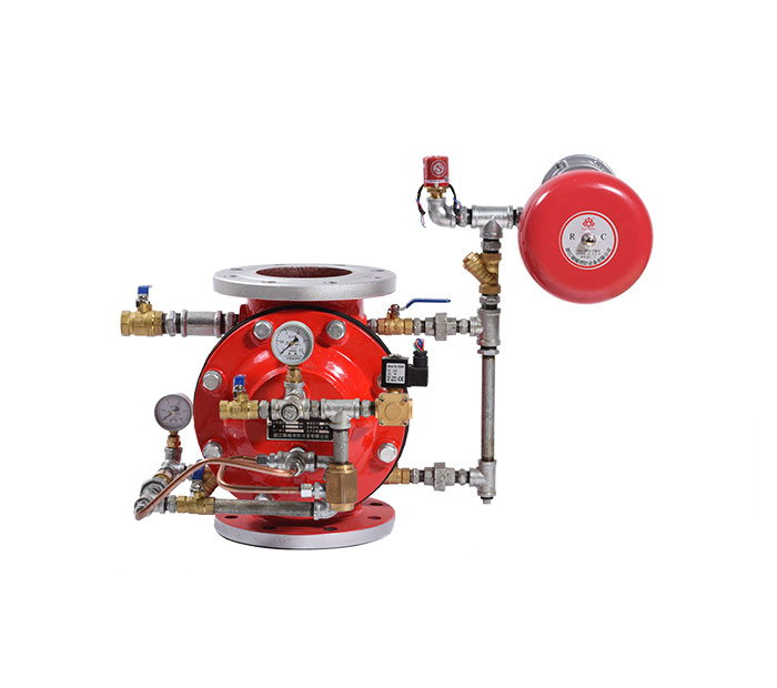
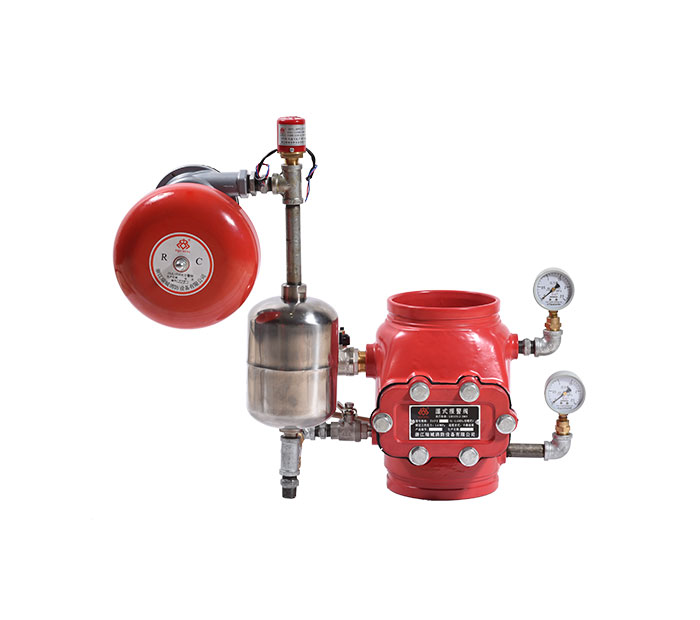
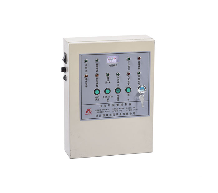
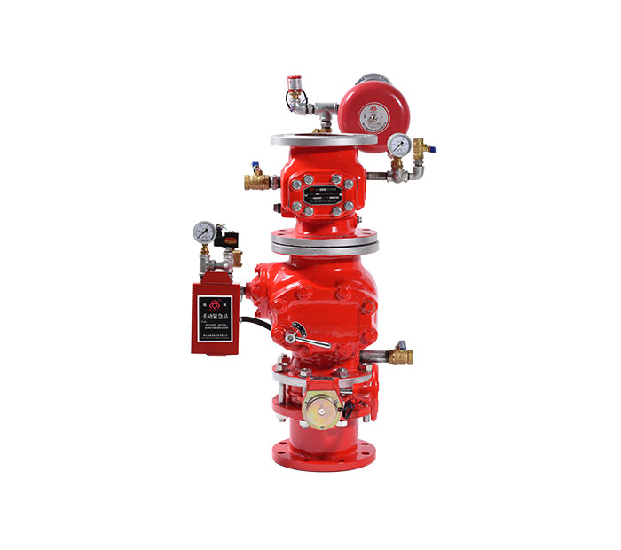
The pre-action device is composed of a pre-action alarm valve group, a control panel, a pneumatic pressure maintaining device and an air supply device, and is turned on by electric, pneumatic, mechanical or other methods, so that water can flow into the water spray system in one direction and simultaneously alarms. To the valve block device.
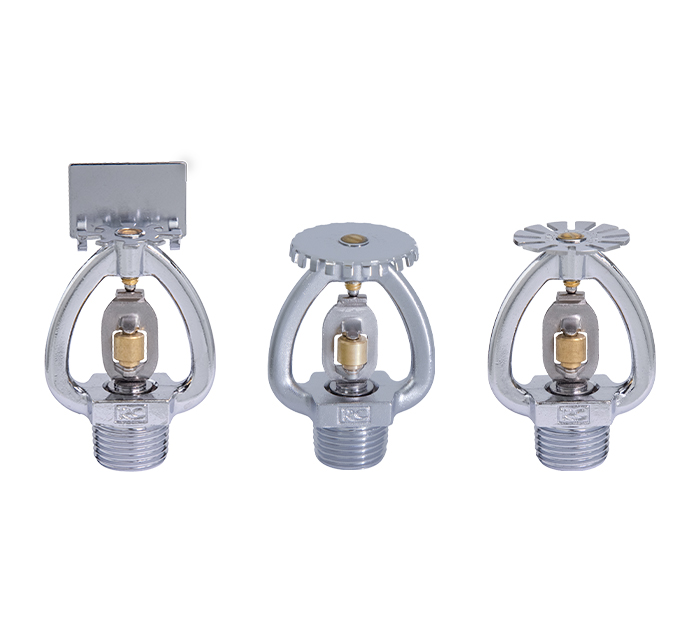
The pre-action device and the closed nozzle, the inflatable device, the water supply facility and the pipeline form a pre-action system, and the water distribution pipe is not filled with water in the quasi-working state. According to the different places of use of the pre-action system, the pre-action device has two automatic control modes, one is only connected by a group of signals of the fire automatic alarm system, and the other is the two sets of pressure switches set by the fire automatic alarm system and the inflation pipe. The signal linkage is turned on.
The pre-action system combines the automatic fire alarm system with the automatic sprinkler system to provide dual protection for the protection object. The pre-action system not only has the characteristics of wet and dry systems, but also avoids the disadvantages of wet and dry systems. Important places where accidental spray or pipeline leakage are not allowed, can be used instead of wet system; instead of dry system in low temperature or high temperature places, it can avoid the disadvantage of delaying water spray after opening.
Product standard: GB5135.14 "Automatic sprinkler system Part 14: Preaction device"
Design Specification: GB50084 "Design Specification for Automatic Sprinkler System"
Acceptance specification: GB50261 "Code for construction and acceptance of automatic sprinkler system".
2、Main performance and technical parameters
|
Rated working pressure |
1.6MPa |
|
Seal test pressure |
3.2MPa |
|
Connection method |
Flange connection |
|
Structural form |
Lever type |
|
Minimum working pressure |
0.25MPa |
|
Working environment temperature |
4℃~70℃ |
|
Solenoid valve working power supply |
DC24V 0.5A |
3、working principle
The water supply side and the control chamber of the preaction device are connected by pipelines, and the pressure water is filled for a long time in the servo state, and the system side is filled with the gas pressure of 0.03 MPa to 0.05 MPa to detect the tightness of the pipeline. When a fire occurs, the fire control center obtains the fire alarm signal of the fire alarm system, and then opens the electromagnetic valve on the alarm valve to make the pressure in the control chamber rapidly decrease, which is greater than the adjustment limit of the orifice plate, and the valve flap assembly is instantly opened. The water on the water supply side flows into the system side to replenish the spray pipe network. The automatic exhaust valve on the spray pipe network empties the air in the pipe network, the anti-reset device prevents the valve from being automatically reset, and the closed nozzle preheats to start the sprinkler. A small part of the water flows to the water alarm bell and the pressure switch. The water alarm bell emits a continuous alarm sound. The pressure switch action feeds the signal back to the fire control center. At the same time, the water supply pump is continuously supplied with water, and the fire control center controls the sound and light alarms. In order to achieve the purpose of automatic sprinkler and alarm.
4、Shape and main connection size

|
1 Connection flange |
8 Alarm isolation ball valve (normally open) |
15Solenoid valve (normally closed) |
22 Control chamber pressure gauge |
||||||
|
2 Water supply side universal valve (normally open) |
9 Alarm test ball valve (normally closed) |
16 Connect the drive tube plug |
23 Manual emergency ball valve (normally closed) |
||||||
|
3 Rain alarm valve (control valve) |
10Water drain plug |
17Watering funnel |
24Pressure control electric contact pressure gauge |
||||||
|
4 Reset handle |
11 Control chamber inlet hose |
18 Water isolation ball valve (normally closed) |
25Alarm feedback electric contact pressure gauge |
||||||
|
5 Wet alarm valve (check valve) |
12Water supply side pressure gauge |
19 Inflatable gate valve (normally open) |
26Quick fill balloon valve |
||||||
|
6 Pressure Switch |
13 Drain valve |
20 Drain ball valve (normally closed) |
27Balloon valve |
||||||
|
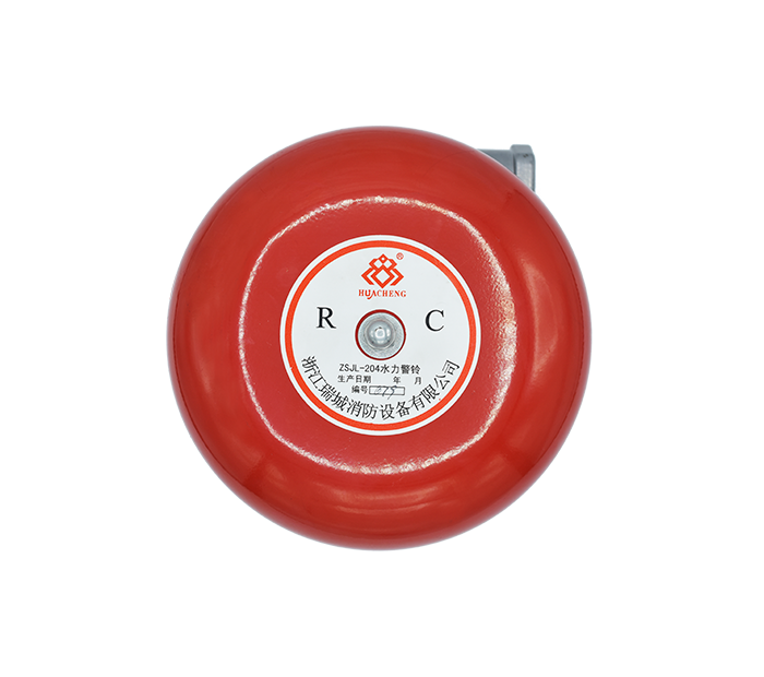
7 Hydraulic alarm |
14 Control chamber pressure gauge |
21 Drain ball valve (normally closed) |
28Pressure reducing valve |
||||||
|
Model |
Nominal diameter | H1 | L1 | L2 | L3 |
|
ZSFY 100-1.6(GC) |
DN100 | 360 | 255 | 305 | 271 |
|
ZSFY 150-1.6(GC) |
DN150 | 427 | 282 | 334 | 323 |
|
ZSFY 200-1.6(GC) |
DN200 | 530 | 307 | 356 | 380 |
|
ZSFY 250-1.6(GC) |
DN250 | 635 | 338 | 390 | 451 |
Ruicheng Fire

Mobile Phone Version
Zhejiang Ruicheng Fire Equipment Co., Ltd.
Address: Binhai New City Industrial Park, Hairun Street, Sanmen County, Zhejiang Province
support hotline:
0576-83369588
0576-89330555
E-mail:
E-mail:[email protected]